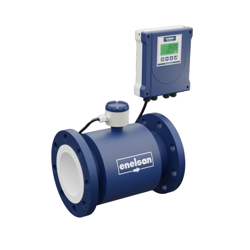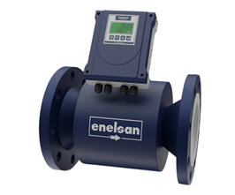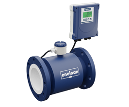
SEPARATE HEAD ELECTROMAGNETIC FLOWMETER
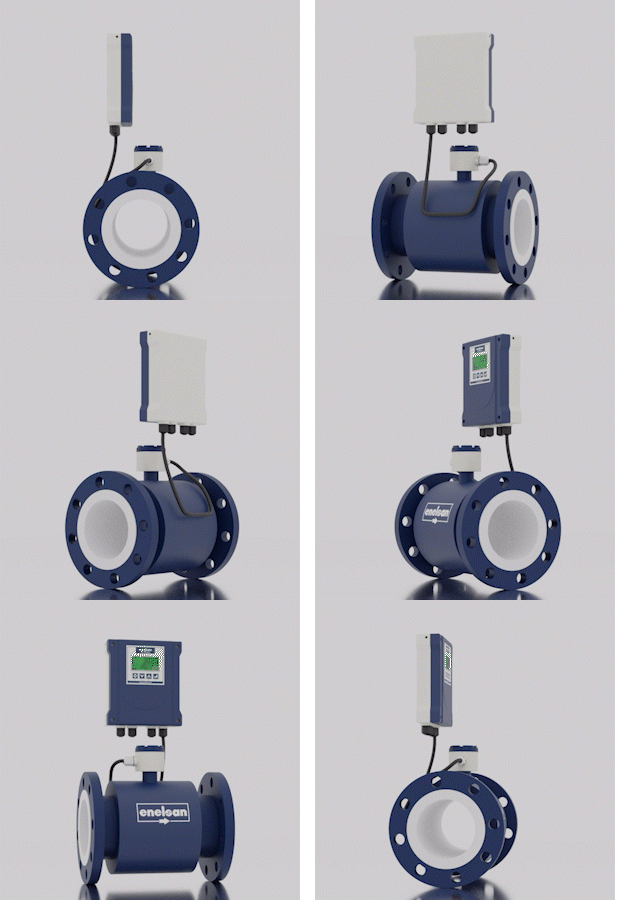 Split Head Electromagnetic Flowmeters can be easily used in all liquids with conductivity over 20 uS. They provide a healthy and long-lasting measurement opportunity by changing the sensor selection in liquids with corrosive properties according to different substances. The inner surface can be preferred as rubber or PTFE. The device, allowing density adjustment, flow unit adjustment, and temperature adjustment, can be used safely in different liquids with any density. The device menu is user-friendly and has 4 different encryption and security settings.
General characteristics of electromagnetic flowmeters
* Fast response time and high stability
* High sensitivity up to 0.2% *Double housing cavity to separate the electronics partition
* AC power or 24VDC supply option * RS485; RS232; HART; Profibus;
MODBUS etc. communication options
* 2-way measurement (forward (positive) measurement and reverse (negative) measurement) and NET total feature * Analog, Frequency and Pulse output features
* Lower limit and upper limit alarm output features
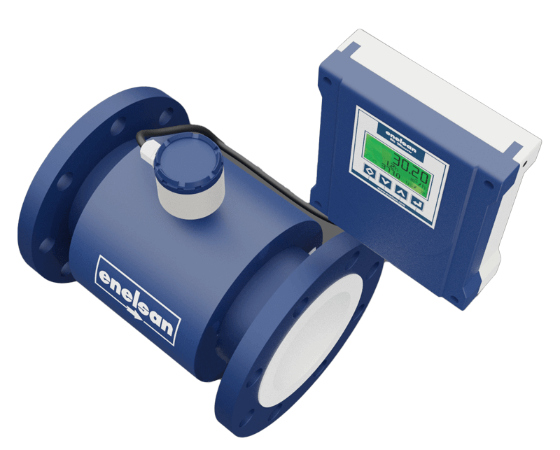
ADVANTAGES OF ELECTROMAGNETIC FLOWMETERS OVER OTHER FLOWMETERS
· There are no mechanical parts that prevent the flow and reduce the pressure.
· Measurement scale; It is 10 times more than other flow meters.
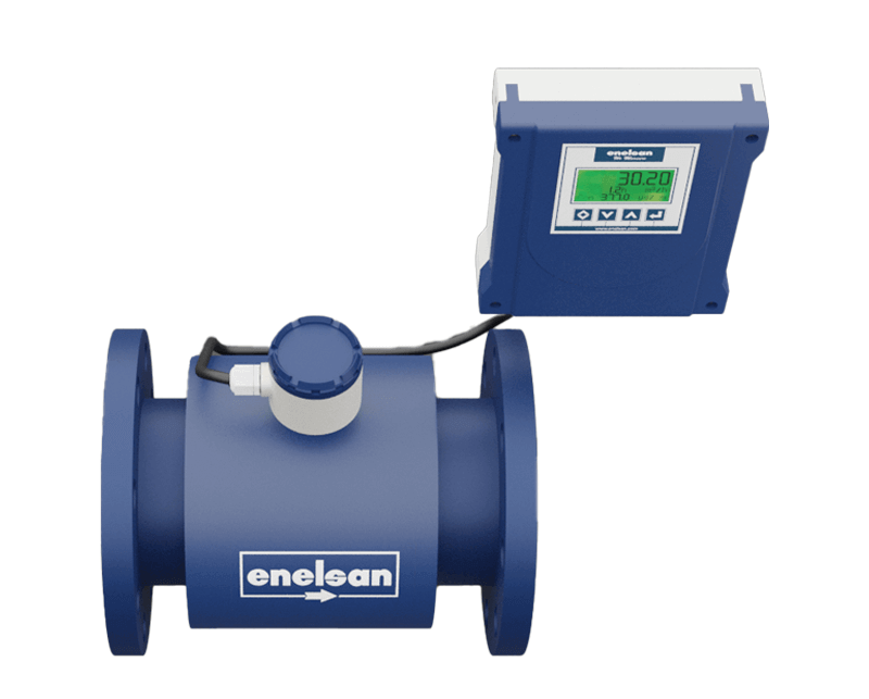
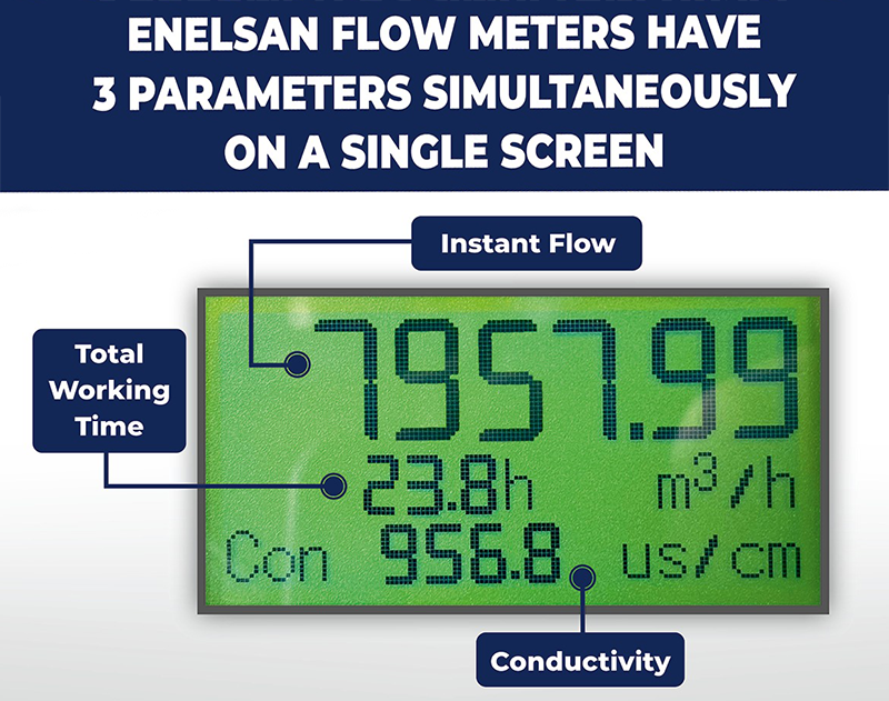
· All measurements and adjustments can be made/displayed via the integrated or wall-mounted LCD screen. It can be composed according to the process and fluid with the user interface (Density setting can be entered)
· The menu can be protected with a password.
· Simultaneously, instantaneous and total flow can be observed on the LCD screen.
. With the report feature, old data can be examined (daily, weekly, monthly, yearly)
. Total flow can only be reset with a password.
· Flow rates between 0.3 and 15 m/s can be measured and the speed can be monitored on the LCD screen.
· Calibration (full-filled and stable fluid-filled pipe) can be done with the menu.
· Measurement accuracy can be achieved as 0.2% ·
Conductivity measurement can be made and displayed on the LCD screen.
· It can take measurements in all homogeneous conductive liquids above 5 uS. It provides resistance to environmental electronic noises through its grounding electrode.
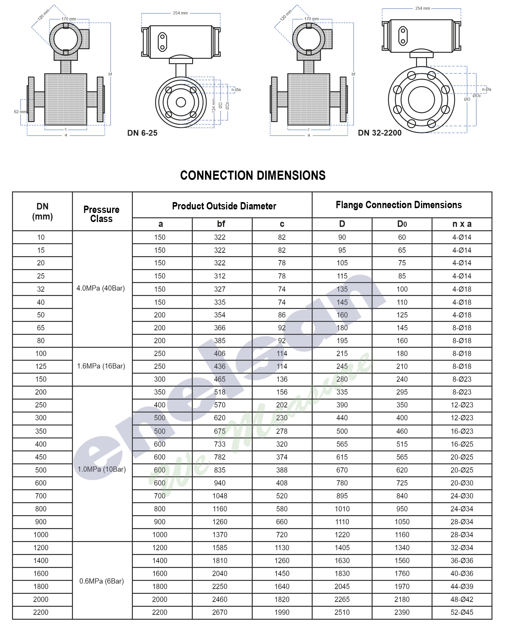
· Thanks to its flange connection, it provides reliable, easy and long-lasting mounting feature. It is protected against external factors thanks to its metal body.

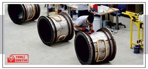
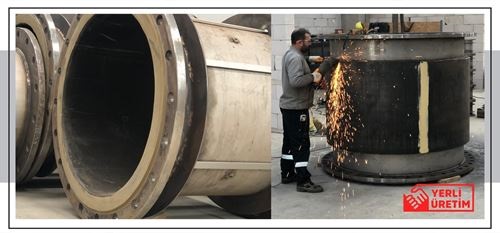
WHAT DO WE PROVIDE WITH DOMESTIC PRODUCTION OF ELECTROMAGNETIC FLOWMETER?
· Measurement stability has been significantly increased.
· The measurement response speed is greatly improved, even with low conductivity and high density. · Electrode material safety has been increased to the highest level.
· With the DN15-DN2200 production facility, the lead times have been minimized.
· LCD display resolution has been increased. · The product electronics has been revised to make it better, more stable and more robust.
· Technical support capacity has been increased and failure support and resolution times have been shortened.
· With our new calibration facility, TÜRKAK accredited services have been provided on a wide scale from DN15 to DN2200.
HOW THE ELECTROMAGNETIC FLOWMETER WORKS:?
Electromagnetic Flow measurement; It is a flow measurement method based on the electromagnetic field principle.
The physical foundations of this Principle are based on British Physicist Michael FARADAY, who discovered in 1831 that electric current can be produced with the help of a magnetic field.
In 1941, Swiss Inventor Bonaventura Thurlemann applied this knowledge to conductive liquids passing through pipes and produced the world's first electromagnetic flowmeter.
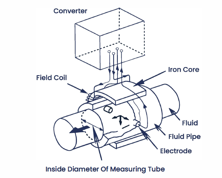
There are 2 coils inside each electromagnetic flowmeter.
With the help of metal parts placed on these coils, it creates a continuous magnetic field across the cross-sectional area of the measuring tube.
The 2 electrodes that sense the voltage are placed inside the measuring tube perpendicular to each other.
The insulating material coated on the inner surface prevents the formation of short circuits between the conductive liquid and the metal measuring tube. In the absence of flow, no electrical tension occurs between the 2 electrodes.
Negatively and positively charged ions in the conductive liquid are in equal amounts in the liquid.
With the initiation of flow, the magnetic field exerts a force on the charged ion particles in the liquid.
As a result, the negatively and positively charged ions in the liquid separate from each other and head to opposite sides of the measuring tube. This results in an electrical voltage sensed by the electrodes.
This voltage is directly proportional to the flow rate in the line.
Instant flow can be calculated with the known volume and velocity information of the measuring tube.
As the flow rate increases, the separation of the charged particles will increase and the voltage between the electrodes will also increase.
The measuring electrodes can also detect magnetic noise in the environment from time to time, this noise signal must be strictly distinguished from the actual measuring signal.
To achieve this, the magnetic field must be created with pulsed direct current.
By constantly changing the places of the charged ions between the electrodes with a direct pulsed current, the effect of magnetic noise is eliminated and precise and stable flow measurement is made.
In the simplest way, the Electromagnetic Measurement principle and the Flow rate information are calculated with the following simplified formula.
HOW TO CHOOSE THE RIGHT PRODUCT? WHAT SHOULD BE CONSIDERED?
Choosing the right product in industrial applications is one of the most important issues. The correct product selection can be made in the light of the information given below. 2/3 of the errors are due to product selection and assembly errors that are not suitable for the process.
1 – The basic information that needs to be obtained and checked is as follows. Fluid name and chemical properties · Maximum, minimum and normal flow amount (or speed information) Maximum pressure
2- The fluid to be measured must have a minimum conductivity of 5 µS/cm.
3- The minimum and maximum flow amount should be suitable for the product measurement range to be selected.
4- The actual maximum pressure must be below the maximum pressure resistance of the flowmeter.
5- The maximum and minimum temperatures must be in accordance with the temperature resistance range of the flowmeter.
6- It should be sure that there is no vacuum on the line.
Electromagnetic flowmeters are not suitable for vacuum. After making sure that this information is correct, the availability of EM flowmeters is ensured and the selection is made according to the flow amount. If the current line diameter and the selected flow meter line diameter are not the same, it should be adjusted with reduction.
Things to consider in this case:
1- It should be evaluated whether the reduction application causes a pressure change in the line, and if there is, whether this change will affect the current flow. In order to avoid this situation, it is not recommended to make large diameter changes in the reductions.
2- When the reduction is preferred to reduce the cost of the flowmeter, it will not be the right choice if the cost of the reduction application is the same or more than the savings obtained in the selection of the flowmeter.
3- In clean water measurements, the most effective measurement is taken at 2-3 m/sec speeds. In liquids that can easily solidify, crystallize or collapse, the flow rate should be above 2 m/s in order to avoid contamination or accumulation on the electrodes. This delays the contamination of the electrodes and allows continued use in contaminated water for longer periods without the need for cleaning.
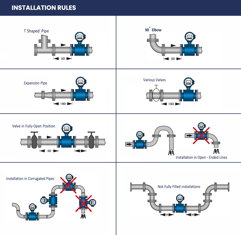
The product should not be exposed to mechanical vibration in the process in which it is used, and should be kept away from impacts and similar factors. If the product is exposed to strong vibration, it may affect the flowmeter itself or its measurements. The assembly rules specified in the catalog and user manuals must be strictly followed. Flow meter should not be installed on the line while welding is being done. If it happens, the product electronics may be damaged. The product should not be exposed to water hammer, even if water is given for the first time, it should be given gradually. The product can even be mounted vertically and horizontally. In vertical mounting, the flow must be from bottom to top. Considering that the compact models are IP67, they should be protected from external factors. Necessary precautions should be taken as exposure to direct sunlight will damage the product screen in all models. Users are strongly recommended to review the product manual thoroughly.
